ACG v1 : Preliminary test results
ACG v1丗帠慜偺帋尡寢壥
Tests by
Jean-Louis Naudin
僔儍儞亖儖僀Naudin偵傛傞僥僗僩
Created on December 15th, 2002 - JLN Labs - Last update December
15th, 2002
2002擭12寧15擔偵偮偔傝傑偡亅JLN尋媶幒2002擭12寧15擔乮嵟廔峏怴乯
Toutes
les informations et schemas sont
publies gratuitement (
freeware ) et sont destines a un usage personnel et
non commercial
et偑sont偡傞et僗僉乕儅sont側publies gratuitement乮僼儕乕僂僃傾乯偑傕偺巊梡恖堳et旕僐儅乕僔儍儖傪梊掕偡傞偲偄偆Toutes les忣曬
All informations and diagrams are published freely
(freeware) and are intendedfor a private use and a non commercial
use.
慡偰偺忣曬偲恾偼巹揑巊梡偲旕彜梡棙梡偺偨傔偵丄帺桼偵岞昞乮僼儕乕僂僃傾乯偱偁傞丄堄枴偝傟傑偡丅
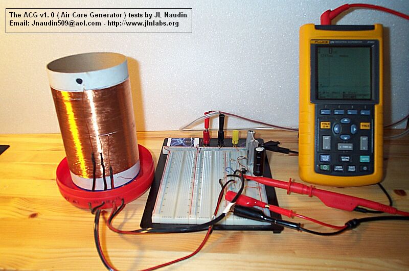
This a preliminary test with the ACG v1.0 ( Air Core
Generator), the ACG name has been invented by Joe Arnold. The ACG principle is
based on the Tesla U.S. Patent 577,670 from 1897. The coil
used is a old air core coil that I have used during my TEP project, the coil is
composed of two coils connected in series, the ACG v1.0 total inductance is
2.07 mH ( 4.6 ohms ). The clock pulses are generated
with a Centrad GF 763AF function generator set at 4.2
KHz ( 28% -DTC ). A N-Channel MosFet transistor BUZ
74, send positive pulses ( +12 V ) at 4.2 KHz at 28% +DTC to the ACG
coil. The function generator is fully isolated from the ACG driver by a 4N25 opto-coupler. All the mesurements
have been done with a fully ungrounded and battery powered digital oscilloscope Fluke 123. 偙偺丄弨旛偼僕儑乕丒傾乕僲儖僪偺柤慜偑敪柧偝傟偨ACG傪ACG v1.0乮嬻婥僐傾敪惗婍乯偱僥僗僩偟傑偡丅
ACG尨懃偼丄1897偐傜僥僗儔丒傾儊儕僇摿嫋577,670偵婎偯偒傑偡丅
巊傢傟傞僐僀儖偼巹偺TEP僾儘僕僃僋僩偺娫丄巊偭偨丄僐僀儖偱丄2偮偺僐僀儖偐傜惉傞屆偄嬻婥僐傾丒僐僀儖偱偡丅僔儕乕僘丄ACG v1.0憤僀儞僟僋僞儞僗偼2.07mH乮4.6僆乕儉乯偱偡丅
763AF僼傽儞僋僔儑儞僕僃僱儗乕僞乕偑4.2kHz偱僀儞僷儖僗偟丄岦怱偺GF偱丄僋儘僢僋僷儖僗傪敪惗偟傑偡乮28%-DTC乯丅
値宆偺MosFet僩儔儞僕僗僞乕BUZ
74偼丄ACG僐僀儖偵28%偺+DTC偱4.2kHz偱億僕僥傿僽側僷儖僗乮+12V乯傪憲傝傑偡丅
僼傽儞僋僔儑儞僕僃僱儗乕僞乕偼丄4N25僆僾僩僇僢僾儔乕偵傛偭偰姰慡偵ACG僪儔僀僶乕偐傜暘棧偝傟傑偡丅
慡偰偺寁應偼丄姰慡偵崻嫆偑側偔僶僢僥儕乕偺尨摦椡偺僨僕僞儖丒僆僔儘僗僐乕僾Fluke 123偱偝傟偨丅
The circuit that I have used for this test is fully based
on the electronic diagram that Jean-Michel Cour has
sent to me, I have just only adpated some components.
I am grateful to Jean-Michel Cour, Joe Arnold and Tim
Harwood for their helpful contribution to this projet. 巹偑偙偺僥僗僩偺偨傔偵巊偭偨夞楬偼丄姰慡偵揹巕恾偵婎偯偒傑偡
僕儍儞亖儈僔僃儖Cour偑巹偵屻傪捛傢偣偨
巹偼丄偪傚偆偳崱庒姳偺峔惉梫慺傪adpated廋惓偟偨偩偗偱偟偨丅
巹偼丄僕儍儞亖儈僔僃儖偵姶幱偟傑偡偍傗丄偙偺寁夋偵懳偡傞斵傜偺栶偵棫偮峷專偺偨傔偺僕儑乕丒傾乕僲儖僪偲僥傿儉丒僴乕僂僢僪丅
Download the N-Channel MosFet transistor BUZ
74
値宆僠儍僱儖MosFet僩儔儞僕僗僞乕傪僟僂儞儘乕僪偟傑偡BUZ
74
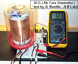
Voltage across the ACG coil ( clock pulse at 4.2 KHz at 28 % +DTC ).
ACG僐僀儖乮28%偺+DTC偺4.2kHz偺僋儘僢僋僷儖僗乯傪搉偭偨揹埑丅
The mesured voltage spikes across the ACG coil are
very strong ( up to 336 V ).
ACG僐僀儖偱寁應偝傟偨揹埑僗僷僀僋偼丄旕忢偵嫮偄乮嵟崅336V乯丅
The Power input is weak : 120 mW ( 12V @ 10 mA )
擖椡偼丄庛偄偱偡丗120mW乮12V仐10mA乯
The voltage spikes across the ACG coil are able to charge a tank capacitor.
Above, the Voltage across the capacitor C2 ( C=160兪F / 350 V )
ACG僐僀儖傪搉偭偨揹埑僗僷僀僋偼丄僞儞僋丒僐儞僨儞僒偵廩揹偡傞偙偲偑偱偒傑偡丅忋偱僐儞僨儞僒C2傪搉偭偨揹埑乮C=160兪F/350V乯
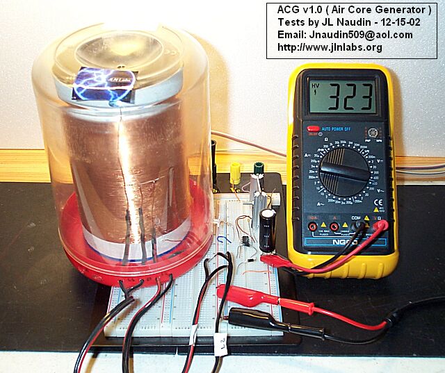
Comment from JL Naudin: The ACG V1.0 circuit works well with a such
air core. The voltage measured across the tank capacitor C2 goes up to 320 V (
and more ) in few seconds. At this moment, I confirms the Jean-Michel Cour and Tim Harwood tests and measurements about the ACG
device... ACG V1.0夞楬偲嬻婥僐傾偼丄傛偔摦偒傑偡丅
僞儞僋丒僐儞僨儞僒C2偱應傜傟偨揹埑偼丄傎偲傫偳昩偱320V偱丄偦傟埲忋偼偁偑傝傑偣傫丅
尰嵼丄巹偼僕儍儞亖儈僔僃儖Cour傪妋偐傔偰偄傑偡丄偦偟偰丄ACG憰抲偵偮偄偰偺僥傿儉丒僴乕僂僢僪丒僥僗僩偺幚尡偲..
朄...
Direct link to the Harwood's ACG web site :
僴乕僂僢僪偺ACG僂僃僽僒僀僩傊偺捈愙揑側儕儞僋丗
- The
Nikola Tesla Patent US577670
俶丒僥僗儔摿嫋US577670 - The
ACG ( Air Core Generator ) based on the Tesla's patents by Tim Harwood
僥僗儔偺摿嫋偵婎偯偔ACG乮嬻婥僐傾敪惗婍乯僥傿儉丒僴乕僂僢僪偵傛偭偰 - The
Tesla Radiant energy, the Quest of Negative Energy by Tim Harwood
僥僗儔曻幩僄僱儖僊乕乮晧僄僱儖僊乕偺扵嶕乯僥傿儉丒僴乕僂僢僪偵傛偭偰
![]() Email : JNaudin509@aol.com
Email : JNaudin509@aol.com
揹巕儊乕儖丗JNaudin509@aol.com
Return to the POD project home page
婣傝傑偡偝傗僾儘僕僃僋僩丒儂乕儉儁乕僕
俹俬俠儅僀僐儞偺奣梫
|
俹俬俠儅僀僐儞偼堦斒偵儚儞僠僢僾儅僀僐儞偲屇偽傟偰偄傞僨僶僀僗偺堦偮偱丄偁傞寛傑偭偨摥偒傪偡傞LSI偱偼柍偔丄儐乕僓乕偑偝傑偞傑側僾儘僌儔儉傪彂偒崬傫偱栚揑偺夞楬傗婡擻傪嶌傝忋偘傞僾儘僌儔儈儞僌宆偺僨僶僀僗偱偡丅
|
丂